Showing posts with label power. Show all posts
Showing posts with label power. Show all posts
Thursday, January 9, 2014
Simple Low Power Switching Regulator Circuit Diagram
This is the Simple Low Power Switching Regulator Circuit Diagram. A simple battery-powered switching regulator provides 5 V out from a 9-V source with 80% efficiency and 50 mA output capability. When Q1 is on, its collector voltage rises, forcing current through the inductor. The output voltage rises, causing A1`s output to rise.
Low Power Switching Regulator Circuit Diagram

Q1 cuts off and the output decays through the load. The 100-pF capacitor ensures clean switching. The cycle repeats when the output drops1ow enough for A1 to turn on Ql. The 1-
Wednesday, May 1, 2013
9V Battery Replacement Power Supply
This circuit was originally designed to power a motorcycle intercom from the vehicle supply system. This type of intercom, which is used for communication between driver and passenger, generally requires quite a bit of power. In order to improve intelligibility there is often elaborate filtering and a compander is sometimes used as well. The disadvantage is that a battery doesn’t last very long. You could use rechargeable batteries, of course, but that is often rather laborious. It seems much more obvious to use the motorcycle power supply instead. A 9-V converter for such an application has to meet a few special requirements.


For one, it has to prevent interference from, for example, the ignition system reaching the attached circuit. It is also preferable that the entire circuit fits in the 9-V battery compartment. This circuit meets these requirements quite successfully and the design has nonetheless remained fairly simple. In the schematic we can recognize a filter, followed by a voltage regulator and a voltage indicator. D1, which protects the circuit against reverse polarity, is followed by an LC and an RC filter (C3/L1/L2/C1/R1/C2). This filter excludes various disturbances from the motorcycle power system.
Moreover, the design with the 78L08 and D3 ensures that the voltage regulator is operating in the linear region. The nominal system voltage of 14 V can sometimes sag to about 12 V when heavy loads such as the lights are switched on. Although the circuit is obviously suitable for all kinds of applications, we would like to mention that it has been extensively tested on a Yamaha TRX850. These tests show that the converter functions very well and that the interference suppression is excellent.
Moreover, the design with the 78L08 and D3 ensures that the voltage regulator is operating in the linear region. The nominal system voltage of 14 V can sometimes sag to about 12 V when heavy loads such as the lights are switched on. Although the circuit is obviously suitable for all kinds of applications, we would like to mention that it has been extensively tested on a Yamaha TRX850. These tests show that the converter functions very well and that the interference suppression is excellent.
Labels:
9v,
battery,
power,
replacement,
supply
Friday, April 12, 2013
ATX Power Switch Substitute
An additional push-button switch is normally required for the ATX Power Switch/Soft Power Switch signal, but you can do without it if you use this simple circuit. It is an artful design, but it has been repeatedly tested. The zener diode is intended to provide protection against excessive voltages and reverse-polarity connection. In the latter case, the resulting short-circuit current (approximately 1A) will exceed the allowable limit and cause the ATX power supply to shut down after around five seconds. It might be possible to use a smaller capacitor; this must be tested experimentally in actual use.
 If the motherboard documentation is poor, you should verify the earth pin using a continuity tester. The resistor is only needed if you want to be able to switch on the PC within ten seconds after switching it off. It discharges the capacitor quickly enough to make this possible. With a 1-kΩ resistor, the time constant is around 0.5 s. Since the capacitor also tends to stabilize the voltage, this circuit could also help in situations in which the ATX power supply switches off unintentionally due to voltage fluctuations on the PWR Supply On line.
ReadMore....
 If the motherboard documentation is poor, you should verify the earth pin using a continuity tester. The resistor is only needed if you want to be able to switch on the PC within ten seconds after switching it off. It discharges the capacitor quickly enough to make this possible. With a 1-kΩ resistor, the time constant is around 0.5 s. Since the capacitor also tends to stabilize the voltage, this circuit could also help in situations in which the ATX power supply switches off unintentionally due to voltage fluctuations on the PWR Supply On line.
Labels:
atx,
power,
substitute,
switch
HANDY 0 12V DC POWER SUPPLY ELECTRONIC DIAGRAM

HANDY 0-12V DC POWER SUPPLY ELECTRONIC DIAGRAM
For heat protection, heat sink is needed for the BD679 transistor. It is because it will be over tempered when works more than 200mA.
FEATURES:
0v to 12 volt output:
- 700mA with M 2155
- 1.4amp with M 2156
- 1A with 16v AC 1.5 amp plug pack
Monday, April 8, 2013
Stereo Hi Fi 20W Mini Audio Power Amplifier
It has explode rainbow light voguish the front panel and very beautiful by night. Light & set Aluminum alloy pencil case on behalf of distribution of roast without doubt RCA Input , can be real used such as Ipod,MP3/MP4 headset amplifier Mini size calm to installation by DIY, especially talented fit for car, motor bike and other audio DIY device.

To Buy Amplifier with Amazon click this link : Lepai TRIPATH TA2020 Class T Mini Amp Hi-Fi Stereo Audio Amplifier
- P.M.P.O,: 2 x 180W, R.M.S.: 2 x 20W
- Input power: 12V 6A DC, (power supply included)
- Input sensitivity: 200mv
- Speaker impedance : 4 - 8ohm
Sunday, April 7, 2013
Small Power Amplifier Circuit
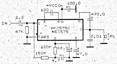
Amplifier circuit is very suitable to be used or applied in a narrow space such as in cars and so forth. Voltage amplifier is needed starting from 9 Volts to 17 Volts maximum. This amplifier circuit uses IC MPC575C, andsimilarities NEC575 . Power output is relatively very small, only 2 Watts.
 |
| Small Power Amplifier Circuit |
8 to 18 volts TDA2005 Power Amplifier
This time, there is a series of audio amplifer 20W as well, but using IC TDA 2005 as a series of his base amplifier. The series of 2x20 Watt Audio Power Amplifier using TDA2005 can you see in the picture below.

Technical Data:
Performance of TDA2005M: (for this circuit); At 4.14 V supply voltage: 2 x 20 watts (stereo) into 4 Ohms.
Distortion: Approx. 0.2% at 4 Watts into 4 ohm load.Frequency Range: Approx. 20 Hz to 22 KHz.
Input Sensitivity: Approx. maximum 150 mV rms. .
Power supply: + 8 to 18 volts, approx. 3.5 Amps maximum per channel.
source [link]
Friday, April 5, 2013
170W power amplifier LM4651 and LM4652
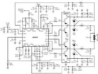
170 Watt power amplifier is a power amplifier that is built by IC LM4651 and LM4652.
Part of this power amplifier driver using the LM4651 IC designed specifically for the purpose of the class AB amplifier driver with short circuit protection feature, containing under voltage, thermal shutdown protection and standby functions. Section 170 Watt power amplifier using LM4651 IC with a MOSFET power amplifier is equipped with temperature sensors that will be used by IC LM4651 as controlnya thermal signal. IC IC LM4651 and LM4652 are designed specifically to each other in pairs to create a class AB power amplifier with protection features are detailed. Detailed series of 170 Watt power amplifier can be seen in thethe following figure .

Power amplifier circuit requires supply voltages +22 V DC symmetrical 0-22V. Power Amplifier with IC LM4651 and LM4652 are often used in portable HiFi systems such as powered speakers, power subwoofer and car audio power Booter. D1, D2, D3 and D4 in series 170 watt power amplifier with LM4651 and LM4652 is a 22V zener diode.
ReadMore....
Part of this power amplifier driver using the LM4651 IC designed specifically for the purpose of the class AB amplifier driver with short circuit protection feature, containing under voltage, thermal shutdown protection and standby functions. Section 170 Watt power amplifier using LM4651 IC with a MOSFET power amplifier is equipped with temperature sensors that will be used by IC LM4651 as controlnya thermal signal. IC IC LM4651 and LM4652 are designed specifically to each other in pairs to create a class AB power amplifier with protection features are detailed. Detailed series of 170 Watt power amplifier can be seen in thethe following figure .

Power amplifier circuit requires supply voltages +22 V DC symmetrical 0-22V. Power Amplifier with IC LM4651 and LM4652 are often used in portable HiFi systems such as powered speakers, power subwoofer and car audio power Booter. D1, D2, D3 and D4 in series 170 watt power amplifier with LM4651 and LM4652 is a 22V zener diode.
6 to 12 Volt Power Supply Inverter
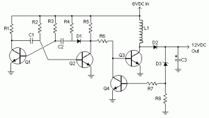
This inverter circuit can provide up to 800mA of 12V power from a 6V supply. For example, you could run 12V car accessories in a 6V (British?) car. The circuit is simple, about 75% efficient and quite useful. By changing just a few components, you can also modify it for different voltages.

Part List:
R1, R4 2.2K 1/4W Resistor
R2, R3 4.7K 1/4W Resistor
R5 1K 1/4W Resistor
R6 1.5K 1/4W Resistor
R7 33K 1/4W Resistor
R8 10K 1/4W Resistor
C1,C2 0.1uF Ceramic Disc Capacitor
C3 470uF 25V Electrolytic Capcitor
D1 1N914 Diode
D2 1N4004 Diode
D3 12V 400mW Zener Diode
Q1, Q2, Q4 BC547 NPN Transistor
Q3 BD679 NPN Transistor
L1 See Notes
MISC Heatsink For Q3, Binding Posts (For Input/Output), Wire, Board
ReadMore....

Part List:
R1, R4 2.2K 1/4W Resistor
R2, R3 4.7K 1/4W Resistor
R5 1K 1/4W Resistor
R6 1.5K 1/4W Resistor
R7 33K 1/4W Resistor
R8 10K 1/4W Resistor
C1,C2 0.1uF Ceramic Disc Capacitor
C3 470uF 25V Electrolytic Capcitor
D1 1N914 Diode
D2 1N4004 Diode
D3 12V 400mW Zener Diode
Q1, Q2, Q4 BC547 NPN Transistor
Q3 BD679 NPN Transistor
L1 See Notes
MISC Heatsink For Q3, Binding Posts (For Input/Output), Wire, Board
source:LINK
Surround Power Amplifier LM3886
Power Amplifier LM3886
Audio Power Amplifier is an important part in the reproduction of sound in a sound system. Audio Power Amplifier LM 3886 with power IC Audio Power Amplifier is a highly capable and able to produce 68 Watts with power rata2 4Ohm load and capable of producing power 38 Watt with 8Ohm load.
With good sound reproduction capabilities of 20Hz-20kHz is also included on this LM3886 Audio Power Amplifier. LM3886 Audio Power Amplifier is equipped with spike protection that will protect the output circuit from overvoltage, undervoltage, overloads, konrsleting power supply, thermal runawaydan peak temperature. Audio Power Amplifier LM3886 also features a noise reduction system which can keep the audio from the noise well.Basic Audio Power Amplifier Series LM3886

Audio Power Amplifier LM3886
Feature owned LM3886 Audio Power Amplifier
68W cont. avg. output power into 4Ω at VCC = ± 28V
38W cont. avg. output power into 8Ω at VCC = ± 28V
50W cont. avg. output power into 8Ω at VCC = ± 35V
135W instantaneous peak output power capability
Signal-to-Noise Ratio ≥ 92dB
An input mute function
Output protection from a short to ground or to the supplies via internal current limiting circuitry
Output over-voltage protection against transients from inductive loads
Supply under-voltage protection, not allowing internal biasing to occur Pls | VEE | + | VCC | ≤ 12V, Thus eliminating turn-on and turn-off transients
11-lead TO-220 package
Wide supply range 20V - 94V
Application of Audio Power Amplifier LM3886
Stereo audio system
Active Speaker
High End Audio Power TV
Suround Power Amplifier
Subscribe to:
Posts (Atom)