Showing posts with label 12. Show all posts
Showing posts with label 12. Show all posts
Monday, August 5, 2013
Simple 12 16V Converter Circuit Diagram
This is simple 12 -16V converter circuit diagram . Many devices operate from a car`s 12-V electrical system. Some require 12 V; others require some lesser voltage. An automobile battery`s output can vary from 12 to 13.8 V under normal circumstances. The load requirements of the device might vary.
This circuit maintains a constant voltage regardless of how those factors change. Simple circuit, A, uses a 7805 voltage regulator.In addition to a constant output, this JC provides overload and short-circuit protection. That unit is a 5-V, 1-A regulator, but when placed in circuit B, it can provide other voltages as well. When the arm of potentiometer R1 is moved toward ground, the output varies from 5 to about 10 V.
Simple 12 -16V Converter Circuit Diagram


Saturday, April 6, 2013
Build a LT3582 12 DC 5V to 12V DC Converter
Using LT3582-12 dual channel DC DC converter integrated circuit, manufactured by Linear Technology, can be designed a very simple step up dc converter. This 5 to 12V c converter electronic project provide both positive and negative outputs required in many biasing applications such as active matrix OLED (organic light-emitting diode)displays as well as CCD (charge coupled device) applications.

The LT3582 offer an I2C interface that can dynamically program output voltages, power sequencing and output voltage ramps as the application requires. The LT3582’s positive output voltage can be set between 3.2V and 12.775 in 25mV steps, whereas the negative output can be set between -1.2V and -13.95V in 50mV steps. The LT3582-12 is preconfigured with ±12V output, requiring no future programming.
Friday, April 5, 2013
6 to 12 Volt Power Supply Inverter
This inverter circuit can provide up to 800mA of 12V power from a 6V supply. For example, you could run 12V car accessories in a 6V (British?) car. The circuit is simple, about 75% efficient and quite useful. By changing just a few components, you can also modify it for different voltages.
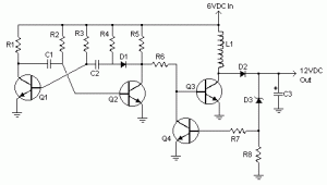
Part List:
R1, R4 2.2K 1/4W Resistor
R2, R3 4.7K 1/4W Resistor
R5 1K 1/4W Resistor
R6 1.5K 1/4W Resistor
R7 33K 1/4W Resistor
R8 10K 1/4W Resistor
C1,C2 0.1uF Ceramic Disc Capacitor
C3 470uF 25V Electrolytic Capcitor
D1 1N914 Diode
D2 1N4004 Diode
D3 12V 400mW Zener Diode
Q1, Q2, Q4 BC547 NPN Transistor
Q3 BD679 NPN Transistor
L1 See Notes
MISC Heatsink For Q3, Binding Posts (For Input/Output), Wire, Board
ReadMore....
Part List:
R1, R4 2.2K 1/4W Resistor
R2, R3 4.7K 1/4W Resistor
R5 1K 1/4W Resistor
R6 1.5K 1/4W Resistor
R7 33K 1/4W Resistor
R8 10K 1/4W Resistor
C1,C2 0.1uF Ceramic Disc Capacitor
C3 470uF 25V Electrolytic Capcitor
D1 1N914 Diode
D2 1N4004 Diode
D3 12V 400mW Zener Diode
Q1, Q2, Q4 BC547 NPN Transistor
Q3 BD679 NPN Transistor
L1 See Notes
MISC Heatsink For Q3, Binding Posts (For Input/Output), Wire, Board
source:LINK
Subscribe to:
Posts (Atom)