Showing posts with label amplifier. Show all posts

Thursday, September 26, 2013

Low Noise Microphone Amplifier OP270E

The signal from a microphone is two weak for a standard line input. This low-noise DC-coupled microphone amplifier provides a solution for anyone who wants to connect a microphone to his or her hi-fi installation. As can be seen from the schematic diagram, a good circuit does not have to be complex. A differential amplifier is built around T1 (MAT-03E), which is a low-noise dual transistor. The combination of T2 and LED D1 forms a constant-current source for the input stage. A low-noise opamp (OP-270E) amplifies the difference signal that appears at the collectors of the dual transistor. The result is an analogue signal at line level.

Low-Noise Microphone Amplifier Circuit Diagram Using Operational amplifier (OP270E)The bandwidth of the amplifier ranges from 1 Hz to 20 kHz. Within the audio range (20 Hz to 20 kHz), the distortion is less than 0.005 percent. Since only half of the OP-270E is used, the remaining opamp could be used in the output stage of a stereo version. The amplifier can be powered from a stabilized, symmetrical supply with a voltage between ±12 V and ±15 V. Such supply voltages are already present in many amplifier.
ReadMore....

Friday, April 12, 2013

Simple Video Amplifier

The video amplifier in the diagram is a well-known design. Simple, yet very useful, were it not for the ease with which the transistors can be damaged if the potentiometers (black level and signal amplitude) are in their extreme position. Fortunately, this can be obviated by the addition of two resistors. If in the diagram R3 and R4 were direct connections, as in the original design, and P1 were fully clockwise and P2 fully anticlockwise, such a large base current would flow through T1 that this transistor would give up the ghost.

 Video Amplifier Circuit diagram :


Moreover, with the wiper of P2 at earth level, the base current of T2 would be dangerously high. Resistors R3 and R4 are sufficient protection against such mishaps, since they limit the base currents to a level of not more than 5 mA. Shunt capacitor C4 prevents R4 having an adverse effect on the amplification.

Source :   http://www.ecircuitslab.com/2011/06/video-amplifier-circuit-diagram.html
ReadMore....

Tuesday, April 9, 2013

Mini Amplifier with 3 Transistor

Mini 3 transistor amplifier is a simple amplifier with 50mW power drawn by 3 transitor.
The series of three mini-amplifier transistors can be used for loud speaker 8 ohm load. Source voltage required to activate the mini-amplifier can be drawn from the batteries 9V.Rangkaian 3 transistor amplifier is often used in simple portabe audio devices such as radios or small tape recorder. Mini-transistor amplifier circuit 3 is quite simple as shown in the figure below.


Mini Amplifier with 3 Transistor


Mini-transistor amplifier circuit 3 includes type of amplifier OTL (Output Transformer Less). Mini-transistor amplifier circuit 3 is used for output coupling capacitors. Amplifier circuit is simple and suitable when used for audio amplifier experiment.
ReadMore....

2 X 0 6W schematic audio amplifier

This schematic have require minimum voltage at 1Volt and maximum volotage at 9 Volt. Maximum output power 2 X 0.6W.

Part List:
Capacitor
C1 = 100uF
C2 = 220uF
C3 = 220uF
C4 = 220uF
C5 = 220uF
IC = ULN3782
ReadMore....

4 20 Volts Amplifier Circuit

This is an audio amplifier circuit based on IC, and IC were used that MPC563 with minimal output 6W, with impedance of 4 Ohm. Supply Voltage Minimum 4 Volt DC and a maximum voltage to 20 Volts DC. See him under this Scheme.
4 - 20 Volts Amplifier Circuit
ReadMore....

Monday, April 8, 2013

Stereo Hi Fi 20W Mini Audio Power Amplifier

It has explode rainbow light voguish the front panel and very beautiful by night. Light & set Aluminum alloy pencil case on behalf of distribution of roast without doubt RCA Input , can be real used such as Ipod,MP3/MP4 headset amplifier Mini size calm to installation by DIY, especially talented fit for car, motor bike and other audio DIY device.

Lepai TRIPATH TA2020 Class T Mini Amp Hi-Fi Stereo Audio Amplifier


  • P.M.P.O,: 2 x 180W, R.M.S.: 2 x 20W
  • Input power: 12V 6A DC, (power supply included)
  • Input sensitivity: 200mv
  • Speaker impedance : 4 - 8ohm

To Buy Amplifier with Amazon click this link : Lepai TRIPATH TA2020 Class T Mini Amp Hi-Fi Stereo Audio Amplifier
ReadMore....

Sunday, April 7, 2013

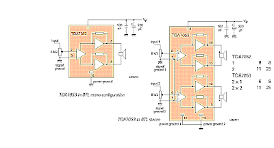
BTL Stereo Amplifier TDA7052 3

This is BTL stereo power amplifier with basic amplifier on IC TDA7052 / TDA7053

BTL Stereo Amplifier TDA7052 / 3
ReadMore....

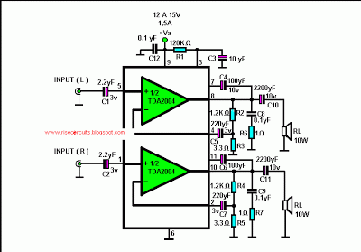
10 10 W Stereo Amplifier with tda2004

Hello! in this post I will show a small amplifier using integrated circuit TDA2004 get two outputs 10 watts, the circuit is very simple, if you want to change the circuit, or a mono version refer to the datasheet tda2004!
The circuit is powered by source between 12 and 15 volts with a current of 1.5 Amperes.
 
See the figure below:
10 +10 W Stereo Amplifier with tda2004

ReadMore....

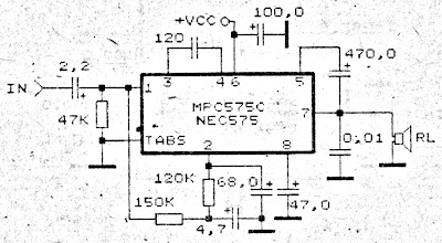
Small Power Amplifier Circuit

Amplifier circuit is very suitable to be used or applied in a narrow space such as in cars and so forth. Voltage amplifier is needed starting from 9 Volts to 17 Volts maximum. This amplifier circuit uses IC MPC575C, andsimilarities NEC575 . Power output is relatively very small, only 2 Watts.
Small Power Amplifier Circuit
ReadMore....

8 to 18 volts TDA2005 Power Amplifier

This time, there is a series of audio amplifer 20W as well, but using IC TDA 2005 as a series of his base amplifier. The series of 2x20 Watt Audio Power Amplifier using TDA2005 can you see in the picture below.


TDA2005 2 X 20 Watt Power Amplifier

Technical Data:
Performance of TDA2005M: (for this circuit); At 4.14 V supply voltage: 2 x 20 watts (stereo) into 4 Ohms.
Distortion: Approx. 0.2% at 4 Watts into 4 ohm load.
Frequency Range: Approx. 20 Hz to 22 KHz.
Input Sensitivity: Approx. maximum 150 mV rms. .
Power supply: + 8 to 18 volts, approx. 3.5 Amps maximum per channel.
source [link] 
ReadMore....

Saturday, April 6, 2013

Fuse Box Toyota 1995 Supra For The Amplifier Diagram

Fuse Box Toyota 1995 Supra For The Amplifier Diagram - Here are new post for Fuse Box Toyota 1995 Supra For The Amplifier Diagram.

Fuse Box Toyota 1995 Supra For The Amplifier Diagram


Fuse Box Toyota 1995 Supra For The Amplifier Diagram

Fuse Panel Layout Diagram Parts: blower motor, center airbag, sensor assembly, cigar lighter, cigar lighter illumination, airbag squib, ashtray illumination, auto antenna control relay, clutch stast switch, combination meter, combination switch, cruise control clutch, daytime running light, ABS laterai acceleration sensor, air inlet control servo motor, amplifier, A/C evaporator temperature sensor, A/C room temperature sensor, solar sensor, ABS ECU.
ReadMore....

Friday, April 5, 2013

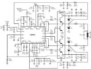
170W power amplifier LM4651 and LM4652

170 Watt power amplifier is a power amplifier that is built by IC LM4651 and LM4652.


Part of this power amplifier driver using the LM4651 IC designed specifically for the purpose of the class AB amplifier driver with short circuit protection feature, containing under voltage, thermal shutdown protection and standby functions. Section 170 Watt power amplifier using LM4651 IC with a MOSFET power amplifier is equipped with temperature sensors that will be used by IC LM4651 as controlnya thermal signal. IC IC LM4651 and LM4652 are designed specifically to each other in pairs to create a class AB power amplifier with protection features are detailed. Detailed series of 170 Watt power amplifier can be seen in thethe following figure .

170W power amplifier LM4651 and LM4652

Power amplifier circuit requires supply voltages +22 V DC symmetrical 0-22V. Power Amplifier with IC LM4651 and LM4652 are often used in portable HiFi systems such as powered speakers, power subwoofer and car audio power Booter. D1, D2, D3 and D4 in series 170 watt power amplifier with LM4651 and LM4652 is a 22V zener diode.
ReadMore....

Surround Power Amplifier LM3886


Power Amplifier LM3886 
Audio Power Amplifier is an important part in the reproduction of sound in a sound system. Audio Power Amplifier LM 3886 with power IC Audio Power Amplifier is a highly capable and able to produce 68 Watts with power rata2 4Ohm load and capable of producing power 38 Watt with 8Ohm load. 
With good sound reproduction capabilities of 20Hz-20kHz is also included on this LM3886 Audio Power Amplifier. LM3886 Audio Power Amplifier is equipped with spike protection that will protect the output circuit from overvoltage, undervoltage, overloads, konrsleting power supply, thermal runawaydan peak temperature. Audio Power Amplifier LM3886 also features a noise reduction system which can keep the audio from the noise well.

Basic Audio Power Amplifier Series LM3886 


Audio Power Amplifier LM3886 

Feature owned LM3886 Audio Power Amplifier 

68W cont. avg. output power into 4Ω at VCC = ± 28V
38W cont. avg. output power into 8Ω at VCC = ± 28V
50W cont. avg. output power into 8Ω at VCC = ± 35V
135W instantaneous peak output power capability
Signal-to-Noise Ratio ≥ 92dB
An input mute function
Output protection from a short to ground or to the supplies via internal current limiting circuitry
Output over-voltage protection against transients from inductive loads
Supply under-voltage protection, not allowing internal biasing to occur Pls | VEE | + | VCC | ≤ 12V, Thus eliminating turn-on and turn-off transients
11-lead TO-220 package
Wide supply range 20V - 94V
Application of Audio Power Amplifier LM3886
Stereo audio system
Active Speaker
High End Audio Power TV
Suround Power Amplifier
ReadMore....

Thursday, April 4, 2013

Hydrophone Booster Amplifier HA2

Hydrophone Booster Amplifier (HA2)
The HP series Hydrophone Booster Amplifier (HA2) amplifies low-level hydrophone signals over a wide range of frequencies. It has a minimum gain of 25dB and an input and output impedance of 50Ω. The HA2 is designed for use with either Precision Acoustics membrane hydrophone or Precision Acoustics HP Series Hydrophone Measurement System, which is shown in Fig 1.
Hydrophone Booster Amplifier
Alternatively, the HA2 may be used when the acoustic signal is provided by a high output impedance hydrophone, such as a GEC-Marconi membrane device, or a conventional hydrophone. In this instance a BNC/MCX adaptor is used which connects directly to the HP Series Submersible Preamplifier, using it as a buffer amplifier, (i.e. the standard Precision Acoustic HP Series configuration shown in Fig 1 is used, but without the interchangeable probe).
The HA2 amplifier is straightforward to use but the following points should be noted:
  • The output of the amplifier should be correctly terminated in 50Ω before operation.
  • The HA2 amplifier is non-inverting but this is of no consequence when used with the HP Series interchangeable probes as their design takes this into account. However when a submersible preamplifier is used as a high impedance buffer amplifier (as in Fig 2) the system output from the HA2 will be inverted as the HP Series Submersible Preamplifier is inverting.
Before Connecting the unit please read WARNING
To Connect
To  Disconnect
1 Connect Output Load 1 Remove RF Input
2 Apply DC Voltage 2 Remove DC Volts
3 Apply RF Input 3 Remove Load

Specification (HA2 Amplifier Only)
Voltage Gain = 25dB minimum
Bandwidth =  50kHz to 125MHz ±1.0dB
Maximum Output Level = 29dBm for 1dB compression (18.1V pk – pk into 50Ω load)
Input Impedance = Nominal 50Ω
Output Impedance  Nominal 50Ω (VSWR 2:1)
Output Noise Level = Typically 70μV pk – pk (bandwidth 125MHz)
Noise Figure = Typically 10dB
Phase = Non-inverting
Terminations:
Front panel = Input BNC socket BNC Output socket
Rear panel Power Requirements = 28v dc output to supply DC Coupler 100/120/220/240V ac, 50 to 60Hz,
7.5W
Operating Temperature = 0 to 50°C
Size = (90mm × 205mm ×194mm)
Weight = 2.6kg


Streampowers
ReadMore....