Wednesday, August 14, 2013
Read Circuit Wiring Diagramsehow

Of Content How To Use This Manual Wiring And Electric Parts Symbols.

How To Read Circuit Wiring Diagrams Ehow Com.

Diagram Electrical Wiring.
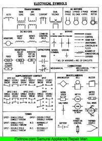
To Read Wiring Diagram Symbols Terminal Codes And Wiring Diagrams.

New Electrical Service Home Residential Wiring Diy Advice.

Common Wiring Diagram Symbols.

Circuit Diagram Software Recommendations Diybanter.

Same Symbols E G Wiring Symbols Http Hampgh Com Classmaterials Aspx.

What Is Schematic Diagram Circuit Schematic.

Wiring Requires Knowledge Of The Symbols Used In Wiring Diagrams.
Sunday, August 11, 2013
Thermometer Based on Mikrokontroler AT89S52


This is a circuit of a microcontroller AT89S52 thermometer and LTC1298 12-bit ADC, programs written in C language program with digital filtering and interface the LED display. Reading provides a sensitivity 0.1C.
The hardware block and circuit diagram is shown in the figure below. The thermistor sensor is epoxy. The signal conditioning circuit is a simple voltage divider. The ADC is 12-bit SPI interface LTC1298 analog to digital. Atmels Microcontroller 89S52. The 0.5 inch display has four digits of 7 segments. The driver of the segment offers 32-bit CMOS output.
The 12-bit ADC (LTC1298 or MC3202) are two channels, CH0 and CH1. The signal from ADC input channel 0 thermistor voltage divider is simple. Channel 1 is available for other sensors. The example shown in the diagram is the HIH-3160 Honeywell Relative Humidity Sensor. The ADC chip interconnects with MCU 89S52 with P1.1, P1.2 and P1.3. The LED display has 4 digits. The CMOS shift register 4094 directly drives the LED
Thursday, August 8, 2013
Multi Position Mains Switch
The circuit shown here was born out of necessity after one of our colleagues had just renovated his kitchen and realized afterwards that there were not enough switches. Obviously he was not too keen to partially demolish the kitchen to install a few additional wires in the already tiled wall. That’s how the idea arose to develop a clever electronic circuit that would operate two lamps with only one switch. All this appeared to be easy to realize by adding a small circuit, consisting of a decade counter, a diode network, two relays and a low voltage power supply.

The schematic shows how simple the design of the ‘multi-position‘ extension really is. K3 is connected to the switched wires that go to the original light. K1 and K2 are the connections for the two new lamps. The operation is simply based on the fact that at every low to high transition at the CLK input of IC1 the active output moves over by one position. In combination with the diode network D4 through D7 this ensures that with a single wall switch it becomes possible to control two outputs. When the mains voltage is applied to K3 for the first time, Q0 will be high and Re1 will be energized.

When the mains switch is briefly switched off and then on again it will have no consequences for the 9-V power supply, because C4 is quite large. But this will result in a trigger pulse on the CLK input, so that Q1 will now be high and via D5 and D6 both relays are energised. After another off/on cycle of the mains switch, Q2 will be high, relay Re1 will de-energise and only Re2 is still activated. If we repeat the off/on cycle once more we’re back at the starting position and only Re1 is energized.

If the switch remains in the ‘off’ position then both relays will also be off. A printed circuit board has been designed for this extension so that the entire circuit will fit without any problems in a waterproof enclosure from OKW, Bopla or Schyller. The 9V transformer is also fitted on the PCB. PCB screw terminals can be used for K1, K2 and K3. Since the circuit is directly connected to the mains voltage we emphasis that the well-known safety rules need to be observed. When making any measurements or performing other operations on the circuit is it absolutely necessary to first break the connection to K3!
 Resistors:
ReadMore....

The schematic shows how simple the design of the ‘multi-position‘ extension really is. K3 is connected to the switched wires that go to the original light. K1 and K2 are the connections for the two new lamps. The operation is simply based on the fact that at every low to high transition at the CLK input of IC1 the active output moves over by one position. In combination with the diode network D4 through D7 this ensures that with a single wall switch it becomes possible to control two outputs. When the mains voltage is applied to K3 for the first time, Q0 will be high and Re1 will be energized.

When the mains switch is briefly switched off and then on again it will have no consequences for the 9-V power supply, because C4 is quite large. But this will result in a trigger pulse on the CLK input, so that Q1 will now be high and via D5 and D6 both relays are energised. After another off/on cycle of the mains switch, Q2 will be high, relay Re1 will de-energise and only Re2 is still activated. If we repeat the off/on cycle once more we’re back at the starting position and only Re1 is energized.

If the switch remains in the ‘off’ position then both relays will also be off. A printed circuit board has been designed for this extension so that the entire circuit will fit without any problems in a waterproof enclosure from OKW, Bopla or Schyller. The 9V transformer is also fitted on the PCB. PCB screw terminals can be used for K1, K2 and K3. Since the circuit is directly connected to the mains voltage we emphasis that the well-known safety rules need to be observed. When making any measurements or performing other operations on the circuit is it absolutely necessary to first break the connection to K3!
 Resistors:
- R1,R2 = 10kΩ
- R3 = 33kΩ
- R4 = 100kΩ
- R5 = 10kΩ
- C1 = 100nF
- C2 = 10µF 63V
- C3 = 4µF7 63V radial
- C4 = 470µF 16V radial
- C5 = 2µF2 63V axial
- D1-D7 = 1N4148
- D8 = 1N4001
- T2,T3 = BC547B
- IC1 = 4017
- IC2 = 78L09
- K1,K2,K3 = 2-way PCB
- terminal block, lead pitch 7.5mm
- T r1 = mains transformer 9V 1.5VA
- B1 = B80C1500 (round case) (80V piv, 1.5A)
- Re1, Re2 = 12V relay
Monday, August 5, 2013
Simple 12 16V Converter Circuit Diagram
This is simple 12 -16V converter circuit diagram . Many devices operate from a car`s 12-V electrical system. Some require 12 V; others require some lesser voltage. An automobile battery`s output can vary from 12 to 13.8 V under normal circumstances. The load requirements of the device might vary.
This circuit maintains a constant voltage regardless of how those factors change. Simple circuit, A, uses a 7805 voltage regulator.In addition to a constant output, this JC provides overload and short-circuit protection. That unit is a 5-V, 1-A regulator, but when placed in circuit B, it can provide other voltages as well. When the arm of potentiometer R1 is moved toward ground, the output varies from 5 to about 10 V.
Simple 12 -16V Converter Circuit Diagram

Friday, August 2, 2013
Happy Couse Very usefull using Schumacher XC103 SpeedCharger
 yes Richard Smith Happy couse Very usefull Schumacher XC103 SpeedCharger Schumacher XC103 SpeedCharge Battery Charger
 It showed up on time and I put it right to work. It operates perfectly. I have had many Shumaker battery chragers in my day and thats why I keep buying them. Works great so easy to use this charger dose it all from my boat batteries or motor home or motorcyle, its all automatic and not cheap junk its really heavy built
Click here to know price and buy Schumacher XC103 SpeedCharge Battery Charger with Engine Start
Subscribe to:
Posts (Atom)