Wednesday, December 25, 2013
Best Electronic Crowbar Circuit Diagram for AC or DC lines

Sunday, December 22, 2013
Photodiode Alarm
Photo-Diode Alarm Circuit diagram

Thursday, December 19, 2013
Luggage Security System

| Select 1 (Pin6) | Select 2 (Pin1) | Sound effect |
| X | X | Police siren |
| VDD | X | Fire-engine siren |
| VSS | X | Ambulance siren |
| “-” | VDD | Machine-gun sound |
Tuesday, October 8, 2013
Lie Catcher
Here is a circuit that you can have fun with your friends. Especially you can catch your girl friend or your boy friend when ever they say lies. Circuit is very simple and you can build it with in few hours. But you will surprise with the results.
.
For two electrodes you can use wires but to get best results use electrode pads which use in the hospitals. Attach the electrode pads to the back of the hand from one inch apart. Make sure meter should be zero before you start. If the person is lying the meter point will get move.
To operate the circuit it needs two voltages separately as shown in the diagram. You can use alkaline batteries for long use or two 4.5 V two power packs if you want.

Saturday, October 5, 2013
2010 Ford Ranger XL Wiring Diagram
 |
| 2010 Ford Ranger XL Wiring Diagram |
Wednesday, October 2, 2013
Electronic Ear for Lego RCX Module
 The operation of the circuit is simple. IC1, which is wired as a non-inverting amplifier, amplifies the microphone signal by a factor of 100. The output signal from the opamp is rectified by D1 and smoothed by C1. Resistor R2 allows the capacitor to discharge. The resulting DC voltage drives IC2, which acts as a buffer. The output of this opamp is connected to the sensor input of the RCX via a 1-kΩ resistor (R1). Just as with the analogue input adapter described elsewhere in this website, the RCX sees a variable resistance value at the sensor input, and it converts this into a measurement value between 0 and 100.
In the idle state, when no sound is sensed, the measurement value lies between 90 and 100. The louder the sensed sound, the lower the measurement value. You can use the light-sensor routine of the Lego software to set the responses to various sound levels. If you use a threshold value of around 85, then a level under 85 will be sensed as a sound signal, while a level above 85 will be sensed as silence. If you clap your hands near the sensor, the circuit will detect this. If you use these ‘observations’ to increment a counter, it is even possible to measure the number of sound pulses within a defined interval, and then to carry out some action based on the result.
Sunday, September 29, 2013
1940 Chevrolet Passenger Electrical Wiring Diagram
 |
| 1940 Chevrolet Passenger Electrical Wiring Diagram |
Thursday, September 26, 2013
Low Noise Microphone Amplifier OP270E
 The bandwidth of the amplifier ranges from 1 Hz to 20 kHz. Within the audio range (20 Hz to 20 kHz), the distortion is less than 0.005 percent. Since only half of the OP-270E is used, the remaining opamp could be used in the output stage of a stereo version. The amplifier can be powered from a stabilized, symmetrical supply with a voltage between ±12 V and ±15 V. Such supply voltages are already present in many amplifier.
Monday, September 23, 2013
A Car Battery Monitor
Just as I was going up a hill, the lights began to dim and the engine coughed. A large semi-trailer loomed in the rear-vision mirror as I pushed the clutch in and tried to restart. My speed was falling rapidly and my lights were blacked out - I was like a sitting duck in the middle of the road, as the semi-trailer came rapidly bearing down on me. I just managed to pull the car off the road, as the semi-trailer came screaming past, missing me by inches! After calling for assistance from the NRMA, the problem was found to be a fault in the alternator, which was failing to charge the battery. The battery voltage had been falling under the heavy load of the lights and at the worst possible time, there was not sufficient power for the lights or the motor.
 After the initial shock wore off, I put on my thinking cap to come up with a PIC-based solution to the problem. What was really needed was a display and a buzzer, to get my attention should the voltage fall outside a specified range. So my design criteria was set, a series of LEDs could indicate the voltage and a buzzer would also be used to warn of problems.
- Visual indication of battery voltage
- Audible warning when voltage becomes low
- Screw terminals for easy connection
- Simple and easy to build
The circuit is based on PIC16F819 18-pin microcontroller which has an analog-to-digital (A/D) input to monitor the battery voltage and outputs capable of driving LEDs directly, to keep the component count down. There are seven LEDs in all, giving a good range of voltage indication. The topmost LED, LED1, comes on for voltages above 14V which will occur when the battery is fully charged. LED2 indicates for voltages between 13.5V and 14V while LED3 indicates between 13V and 13.5V. Normally, one of these LEDs will be on. LED4 covers 12.5V to 13V while LED5 covers 12V to 12.5V. LED6 covers from 11.5V to 12V while LED7 comes on for voltages below 11.5V. These two LEDs are backed up by the piezo chime which beeps for voltages between 11.5V and 12V and becomes more insistent for voltages below 11.5V.
That might seem fairly conservative. After all, most cars will start with no troubles, even though the battery voltage might be a touch below 12V, wont they? Well, no. Some modern cars will happily crank the motor at voltages below 11V but their engine management will not let the motor start unless the voltage is above 11V. So dont think that a modern car will always start reliably. This little battery monitor could easily prevent a very inconvenient failure to start! So lets describe the rest of the circuit. The incoming supply is connected via diode D1 which provides protection against reverse polarity while zener diode ZD1 provides protection from spike voltages.
A standard 7805 3-terminal regulator is then used to provide a stable 5V to the microcontroller. The battery voltage is sensed via a voltage divider using 33kΩ and 100kΩ resistors. This brings the voltage down to within the 0-5V range for the A/D input of the PIC16F819. Port B (RB0 to RB7) of the microcontroller is then used to drive the various LEDs, with current limiting provided via the 330Ω resistor network. RB7, pin 13, drives a switching transistor for the piezo buzzer.
Software:
For the software, the design follows the basic template for a PIC microcontroller. Port A and its ADC (analog-to-digital converter) function are set up while port B functions as the output for the LEDs and buzzer. Once the set-up is complete, a reading will be taken at port RA2, the input for the A/D convertor. This reading is then compared with a series of values to determine the range of the voltage. This is similar to a series of "if" statements in Basic language. If the voltage is found to be within a certain range, the relevant port B pin will be turned on. If the voltage is below 12V, the buzzer will be turned on for a brief period, to signal a low battery condition. As the voltage falls below 11.5V, the frequency of the beeps will increase, to signal increased urgency.
All the parts are mounted on a small PC board measuring 46 x 46mm (available from Futurlec). The starting point should be the IC socket for the PIC16F819, as this is easiest to mount while the board is bare. The next item can be the PC terminal block. The resistors and capacitors can then follow. Make sure the electrolytics are inserted with correct polarity.
 Make sure that you do not confuse the zener (ZD1) with the diode when you are installing them; the diode is the larger package of the two.
Even more important, dont get the 78L05 3-terminal regulator and the 2N3906 transistor mixed up; they come in identical packages. The 78L05 will be labelled as such while the 2N3906 will be labelled "3906". And make sure you insert them the correct way around. The buzzer must also be installed with the correct polarity. The 330Ω current limiting resistors are all in a 10-pin in-line package. There are four green LEDs, two yellow and one red. They need to be installed in line and with the correct orientation.
Testing:
Before you insert the PIC16F819 microcontroller, do a voltage check. Connect a 12V source and check for the presence of 5V between pins 14 & 5 OF IC1. If 5V is not present, check the polarity of regulator REG1 and the polarity of the diode D1. If these tests are OK, insert the IC and test the unit over a range of voltage between 9V and 15V. Make sure that all LEDs come on in sequence and the piezo buzzer beeps for voltages below 12V.
Now it is matter of installing the unit in your car. It is preferable to install the unit in a visible position for the driver. However, it should not obscure any other instruments. The unit should be connected to the cars 12V supply after the ignition switch. This will turn the unit off with the other instruments and prevent battery drain while the motor is not running.
Author :Alan Bonnard Copyright : Silicon Chip Publications Pty Ltd
Friday, September 20, 2013
1995 Mercedes Benz c 220 Wiring Diagram
 |
| 1995 Mercedes-Benz c 220 Wiring Diagram |
Wednesday, September 11, 2013
Wireless Sensor Applications using Dorji’f DRF5150S and DRf4432S Modules

Thursday, September 5, 2013
Sound Operated Switch Circuit

- This sensitive sound operated switch can be used with a dynamic microphone insert as above, or be used with an electret (ECM) microphone. If an ECM is used then R1 (shown dotted) will need to be included. A suitable value would be between 2.2k and 10kohms.
- The two BC109C transitors form an audio preamp, the gain of which is controlled by the 10k preset. The output is further amplified by a BC182B transistor. To prevent instability the preamp is decoupled with a 100u capacitor and 1k resistor. The audio voltage at the collector of the BC182B is rectified by the two 1N4148 diodes and 4.7u capacitor. This dc voltage will
- directly drive the BC212B transistor and operate the relay and LED.
- It should be noted that this circuit does not "latch". The relay and LED operate momentarily in response to audio peaks.
Monday, September 2, 2013
IR illuminator for Night Vision Tv Cameras and Scopes
Circuit Diagram

Wednesday, August 14, 2013
Read Circuit Wiring Diagramsehow

Of Content How To Use This Manual Wiring And Electric Parts Symbols.

How To Read Circuit Wiring Diagrams Ehow Com.

Diagram Electrical Wiring.
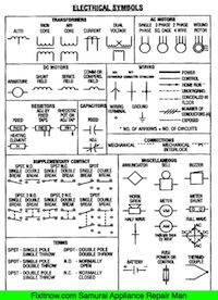
To Read Wiring Diagram Symbols Terminal Codes And Wiring Diagrams.

New Electrical Service Home Residential Wiring Diy Advice.

Common Wiring Diagram Symbols.

Circuit Diagram Software Recommendations Diybanter.

Same Symbols E G Wiring Symbols Http Hampgh Com Classmaterials Aspx.

What Is Schematic Diagram Circuit Schematic.

Wiring Requires Knowledge Of The Symbols Used In Wiring Diagrams.
Sunday, August 11, 2013
Thermometer Based on Mikrokontroler AT89S52


The hardware block and circuit diagram is shown in the figure below. The thermistor sensor is epoxy. The signal conditioning circuit is a simple voltage divider. The ADC is 12-bit SPI interface LTC1298 analog to digital. Atmels Microcontroller 89S52. The 0.5 inch display has four digits of 7 segments. The driver of the segment offers 32-bit CMOS output.
The 12-bit ADC (LTC1298 or MC3202) are two channels, CH0 and CH1. The signal from ADC input channel 0 thermistor voltage divider is simple. Channel 1 is available for other sensors. The example shown in the diagram is the HIH-3160 Honeywell Relative Humidity Sensor. The ADC chip interconnects with MCU 89S52 with P1.1, P1.2 and P1.3. The LED display has 4 digits. The CMOS shift register 4094 directly drives the LED
Thursday, August 8, 2013
Multi Position Mains Switch

The schematic shows how simple the design of the ‘multi-position‘ extension really is. K3 is connected to the switched wires that go to the original light. K1 and K2 are the connections for the two new lamps. The operation is simply based on the fact that at every low to high transition at the CLK input of IC1 the active output moves over by one position. In combination with the diode network D4 through D7 this ensures that with a single wall switch it becomes possible to control two outputs. When the mains voltage is applied to K3 for the first time, Q0 will be high and Re1 will be energized.

When the mains switch is briefly switched off and then on again it will have no consequences for the 9-V power supply, because C4 is quite large. But this will result in a trigger pulse on the CLK input, so that Q1 will now be high and via D5 and D6 both relays are energised. After another off/on cycle of the mains switch, Q2 will be high, relay Re1 will de-energise and only Re2 is still activated. If we repeat the off/on cycle once more we’re back at the starting position and only Re1 is energized.

If the switch remains in the ‘off’ position then both relays will also be off. A printed circuit board has been designed for this extension so that the entire circuit will fit without any problems in a waterproof enclosure from OKW, Bopla or Schyller. The 9V transformer is also fitted on the PCB. PCB screw terminals can be used for K1, K2 and K3. Since the circuit is directly connected to the mains voltage we emphasis that the well-known safety rules need to be observed. When making any measurements or performing other operations on the circuit is it absolutely necessary to first break the connection to K3!
 Resistors:
- R1,R2 = 10kΩ
- R3 = 33kΩ
- R4 = 100kΩ
- R5 = 10kΩ
- C1 = 100nF
- C2 = 10µF 63V
- C3 = 4µF7 63V radial
- C4 = 470µF 16V radial
- C5 = 2µF2 63V axial
- D1-D7 = 1N4148
- D8 = 1N4001
- T2,T3 = BC547B
- IC1 = 4017
- IC2 = 78L09
- K1,K2,K3 = 2-way PCB
- terminal block, lead pitch 7.5mm
- T r1 = mains transformer 9V 1.5VA
- B1 = B80C1500 (round case) (80V piv, 1.5A)
- Re1, Re2 = 12V relay
Monday, August 5, 2013
Simple 12 16V Converter Circuit Diagram

Friday, August 2, 2013
Happy Couse Very usefull using Schumacher XC103 SpeedCharger
 yes Richard Smith Happy couse Very usefull Schumacher XC103 SpeedCharger Schumacher XC103 SpeedCharge Battery Charger
 It showed up on time and I put it right to work. It operates perfectly. I have had many Shumaker battery chragers in my day and thats why I keep buying them. Works great so easy to use this charger dose it all from my boat batteries or motor home or motorcyle, its all automatic and not cheap junk its really heavy built
Click here to know price and buy Schumacher XC103 SpeedCharge Battery Charger with Engine Start
Tuesday, July 30, 2013
Heating System Thermostat Circuit

Parts:
P1 = 1K Linear Potentiometer
R1 = 10R-1/4W Resistor
R2 = 1K-1/4W Resistor
R3 = 3K3 @ 20°C n.t.c. Thermistor (see Notes)
R4 = 2K2 @ 20°C n.t.c. Thermistor (see Notes)
R5 = 10K-1/2W Trimmer Cermet
R6 = 3K3-1/4W Resistor
R7 = 4K7-1/4W Resistors
R8 = 470K-1/4W Resistor
R9 = 4K7-1/4W Resistors
R10 = 10K-1/4W Resistor
C1 = 470µF-25V Electrolytic Capacitors
C2 = 470µF-25V Electrolytic Capacitors
C3 = 1µF-63V Electrolytic Capacitor
D1 = 1N4002 - 100V 1A Diodes
D2 = 1N4002 - 100V 1A Diodes
D4 = 1N4002 - 100V 1A Diodes
D3 = LED Red 3 or 5mm.
Q1 = BC557 - 45V 100mA PNP Transistor
Q2 = BC547 - 45V 100mA NPN Transistor
Q3 = BC337 - 45V 800mA NPN Transistor
J1 = Two ways output socket
T1 = 220V Primary, 12 + 12V Secondary 3VA Mains transformer
PL1 = Male Mains plug &cable
SW1 = SPST Mains Switch
RL1 = Relay with SPDT 2A @ 220V switch Coil Voltage 12V. Coil resistance 200-300 Ohm
When Q1 Base to ground voltage is less than half voltage supply (set by R7 & R9), a voltage is generated across R8 and the driver transistors Q2 & Q3 switch-on the Relay. When Q1 Base to ground voltage is more than half voltage supply, caused when one of the n.t.c. Thermistors lowers its value due to an increase in temperature, no voltage appears across R8 and the Relay is off. C3 allows a clean switching of the Relay. P1 acts as main temperature control.
Notes:
* R3 is the outdoor sensor, R4 the indoor sensor.
* If you are unable to find a 3K3 Thermistor for R3 you can use a 4K7 value instead. The different value can be easily compensated by means of Trimmer R5.
* R5 allows setting the heating system for outdoor temperatures ranging from about +10°C downwards. The higher R5s resistance the hotter the heating system and vice versa.
* The existing boiler thermostat should be set to its maximum value and not bypassed: it is necessary for safetys sake.
* This circuit can be dispensed with its differential feature and converted into a simple precision thermostat omitting R3.
Wednesday, June 12, 2013
Signal Isolation Bags
This designer bags that allow you to isolate the signal can temporarily allow communication devices such as mobile phones from your side "disappear." Lined bags are coated with colloidal silver, both radio frequency isolation, but can also phone sterilization, the true sense of the times you return to no signal. In addition, this signal isolation bags in various sizes, suitable for most currently available mobile phones and tablet PCs. I do not know why, I can not help but think of the iPhone4 "death grip." . .
Friday, May 31, 2013
Wiring Regulationssetting Standards Electrical Installations

City And Guilds Exam Success Iee Wiring Regulations Paperback By.

Guide To The Wiring Regulations 2008 Iee Wiring Regulations Bs 7671.

17th Edition Iee Wiring Regulations.

Iee Wiring Regulations Bs 7671 2008 And Part P Of Building.

Bs 7671 Iee Wiring Regulations 17th Edition.

Iee Wiring Regulations Design And Verification Of Electrical.

Work Updated To Iee Wiring Regulations 17th Edition Bs 7671 2008.

Iee Wiring Regulations Setting Standards In Electrical Installations.

Bathroom Lighting Zones.

Guide To The 15th Edition Of The Iee Wiring Regulations E Book Zella.
Monday, May 13, 2013
Personal Alarm
 This circuit, enclosed in a small plastic box, can be placed into a bag or handbag. A small magnet is placed close to the reed switch and connected to the hand or the clothes of the person carrying the bag by means of a tiny cord.
If the bag is snatched abruptly, the magnet looses its contact with the reed switch, SW1 opens, the circuit starts oscillating and the loudspeaker emits a loud alarm sound.
The device can be reverse connected, i.e. the box can be placed in a pocket and the cord connected to the bag.
This device can be very useful in signalling the opening of a door or window: place the box on the frame and the magnet on the movable part in a way that magnet and reed switch are very close when the door or window is closed.
Sunday, May 5, 2013
Brightness Control for small Lamps
IC1 generates a 150Hz squarewave having a variable duty-cycle. When the cursor of P1 is fully rotated towards D1, the output positive pulses appearing at pin 3 of IC1 are very narrow. Lamp LP1, driven by Q1, is off as the voltage across its leads is too low. When the cursor of P1 is rotated towards R2, the output pulses increase in width, reaching their maximum amplitude when the potentiometer is rotated fully clockwise. In this way the lamp reaches its full brightness.

LP1 could be one or more 1.5V bulbs wired in parallel. Maximum total output current allowed is about 1A.
R2 limits the output voltage, measured across LP1 leads, to 1.5V. Its actual value is dependent on the total current drawn by the bulb(s) and should be set at full load in order to obtain about 1.5V across the bulb(s) leads when P1 is rotated fully clockwise.
Parts:
P1 470K Linear Potentiometer
R1 10K 1/4W Resistor
R2 47K 1/4W Resistor (See Notes)
R3 1K5 1/4W Resistor
C1 22nF 63V Polyester Capacitor
C2 100µF 25V Electrolytic Capacitor
D1,D2 1N4148 75V 150mA Diodes
IC1 7555 or TS555CN CMos Timer IC
Q1 BD681 100V 4A NPN Darlington Transistor
LP1 1.5V 200mA Bulb (See Notes)
SW1 SPST Switch
B1 3V (Two 1.5V AA or AAA cells in series, etc.)
Wednesday, May 1, 2013
9V Battery Replacement Power Supply

Moreover, the design with the 78L08 and D3 ensures that the voltage regulator is operating in the linear region. The nominal system voltage of 14 V can sometimes sag to about 12 V when heavy loads such as the lights are switched on. Although the circuit is obviously suitable for all kinds of applications, we would like to mention that it has been extensively tested on a Yamaha TRX850. These tests show that the converter functions very well and that the interference suppression is excellent.
Tuesday, April 30, 2013
AC 230V Led Circuit Diagram by DIAC

Copyright : CircuitsTune.com
Car Interior Lights Delay
Circuit diagram:

Capacitor C1 is charged fairly rapidly via R3 and D1, whereupon T2 comes on so that the interior light is switched on. When the door is closed again, T1 conducts and stops the charging of C1. However, the capacitor is discharged fairly slowly via R5, so that T2 is not turned off immediately. This ensures that the interior light remains on for a little while and then goes out slowly. The time delays may be varied quite substantially by altering the values of R3, R5, and C1. Circuit IC2 may be one of many types of n-channel power MOSFET, but it should be able to handle drain-source voltages greater than 50 V. In the proto-type, a BUZ74 is used which can handle D-S voltages of up to 500 V.