Showing posts with label crossover. Show all posts
Showing posts with label crossover. Show all posts
Wednesday, April 10, 2013
Crossover For Subwoofer
The crossover network is intended for use when an existing audio installation is to be extended by the addition of a subwoofer. Often, this additional loudspeaker is one that has been lying around for some time. If its frequency response extends down far enough, all is well and good, but a filter is then needed to cut off any frequencies above, say, 150 Hz. Often, a subwoofer network is an active filter, but here this would necessitate an additional power supply. The present network is a passive one, designed so that the speaker signal of the existing system can be used as the input signal.
Crossover For Subwoofer Circuit diagram:

Since the bass information is present in both (stereo) loudspeakers, the signal for the sub woofer can simply be tapped from one of them. The network is a 1st order low-pass filter with variable input (P1) and presettable cut-off frequency (P2). The signal from the loudspeaker is applied to terminal ‘LSP’. Voltage divider R1-R2-P1 is designed for use with the output signal of an average output amplifier of around d 50 W. The crossover frequency of the network may be varied between 50 Hz and 160 Hz with P2. The values of R3, P2, and C1, are calculated on the assumption that the subwoofer amplifier to be connected to K1 has a standard input resistance of 47 kΩ.
If this figure is lower, the value of C1 will need to be increased slightly. It is advisable to open the volume of the subwoofer amplifier fully and adjust the sound level with P1. This ensures that the input of the subwoofer amplifier cannot be overloaded or damaged. Make sure that the ground of the loudspeaker signal line is linked to the ground of the subwoofer amplifier. If phase reversal is required, this is best done by reversing the wires to the subwoofer. If notwithstanding the above additional protection is desired at the input of the subwoofer amplifier, this is best effected by ‘overload protection ’ elsewhere in this site.
Author: T. Giesberts Copyright: Elektor Electronics
Source: http://www.ecircuitslab.com/2011/06/crossover-for-subwoofer.html

Tuesday, April 9, 2013
2 Way Speaker Crossover circuit
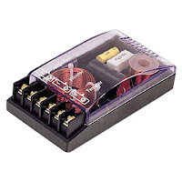
The series of crossover is an electronic circuit in which the point to separate the audio sound frequency. objective that only sound with a frequency range that can be accepted speakers are forwarded. less is more like a filter function, so the speakers work optimally.
2 way or 3 way or else, that determines how many channels would be separated voice. Each channel is handled by a single class of speakers. Eg 3 way, the frequency of sound produced by the head unit, separated by crossover as a low freq (big size distinguished speaker better known as the subwoofer), medium freq (medium speakers), usually in the middle) and hi freq (small speakers I would call a tweeter) Let me better sound and reduce noise.
2 way or 3 way or else, that determines how many channels would be separated voice. Each channel is handled by a single class of speakers. Eg 3 way, the frequency of sound produced by the head unit, separated by crossover as a low freq (big size distinguished speaker better known as the subwoofer), medium freq (medium speakers), usually in the middle) and hi freq (small speakers I would call a tweeter) Let me better sound and reduce noise.
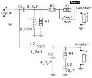 |
| Schematic 2 Way Speaker Crossover |
Subscribe to:
Posts (Atom)